I need some linear motion for a new project and I decided to disassemble an old dot matrix printer in order to reuse its stepper(s), by controlling them via a A4988 stepper driver.
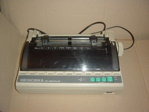
The printer was labeled Philips NIMS 1433 PLUS, but after some discussion on FB it turned out that the original model was Seikosha SP-1900 Plus or 2400.
FB user G. Toscano provided the picture below and the service manual in the attachment section.
Once I removed the cover, this was the situation:
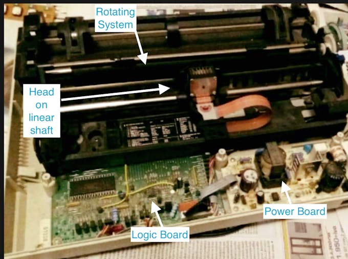
There are two stepper motors, one for the printing head to move left and right, on a linear shaft, and one for the paper roll.
Power
From the service manual they seem to be fed with 24v. This is a voltage I decided to take directly from the power board of the printer, which splits the AC 220V in different voltages. This is part of the scheme of the power board:
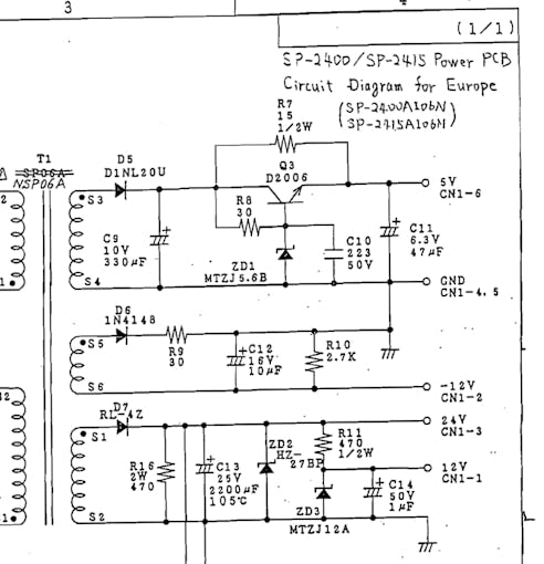
From here we can infer which voltage must be present in the six areas of the power board:
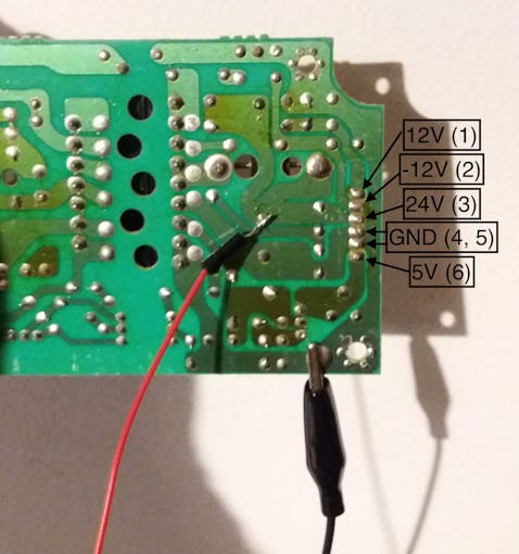
However, by testing with a multimeter, outputs 1 and 2 did not provide any voltage, while output 6 provided 8.2 Volts. I am not enough good at reading circuits to understand if this was in some way intended in the scheme, or if the board is broken, whereas other suggested that it may depend on the fact that there is no actual load on the power board.
Later on, I decided to use the 8.2V output to power the Arduino.
The motors
I found a guide on Instructables in order to understand how to identify the wires connected to the two motors I found in the printer. The motors have six wires each, but we need to use only four of them.
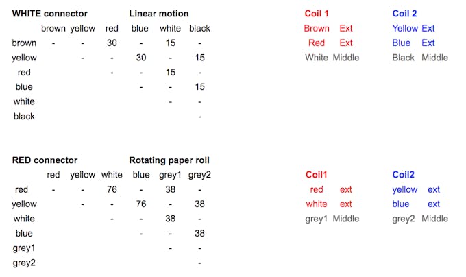
To identify the different wires, and which ones I had to use, I had to test the resistance between the six wires.
We know that the motor has two coils; each coil is connected to three wires. Of those three, two are at the ends of the coil and one is at the middle. This means that the two wires that are connected at the ends will have a bigger resistance; those are the ones we need to use. After filling up a table with the resistance values, it's easy to determine which ones are the two couples of wires connected at the ends of the two coils, and those are the ones we need to connect to the A4988 driver.
The circuit
After testing the circuit (see the attached schematics) with an Arduino UNO and a breadboard, I went for a Nano. Everything is squeezed now on a 3x7 board, which is powered by the comparatively huge original printer power module (with a nice big I/O button).
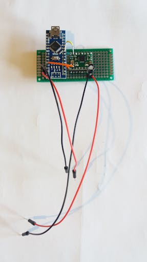
This tutorial on Howtomechatronics, as well as this POLULU page explaining the use of the A4988, were the starting point for my final circuit and the code.
Further developements
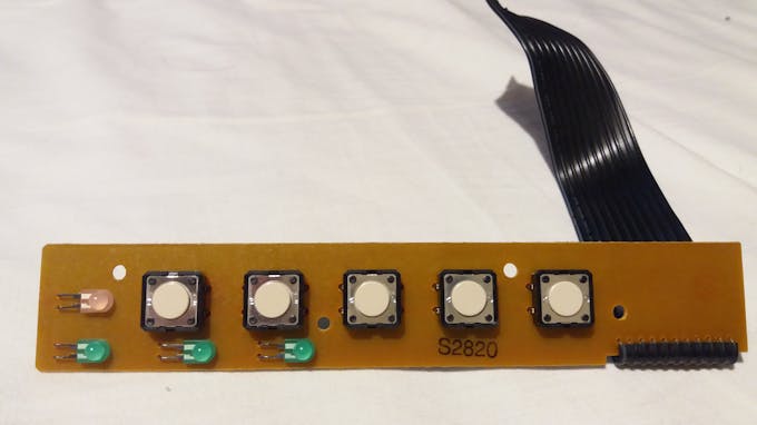
The circuit is very basic. What I would like to add in the next steps is the Sleep control, which will let me save power, diminish the heat and unlock the motor. Different button inputs could be added through the Nano analog pins, with the appropriate resistors, in order to manually bring the head to the desired position (left and right control), start a movement routine, enable sleep mode and so on. Feedback to the user will be given through LEDs.
For this purpose I would use the ready-made control panel of the printer, which you can see in the following pictures:
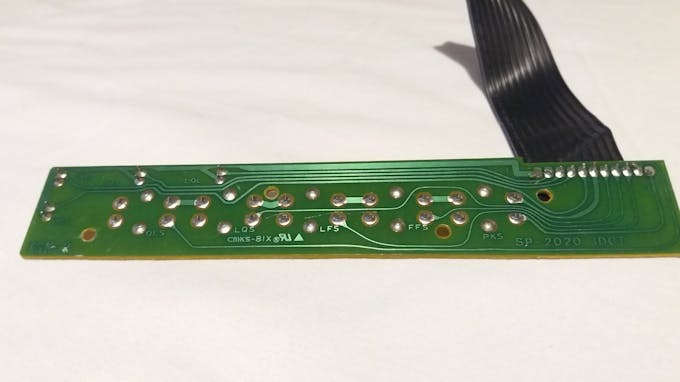
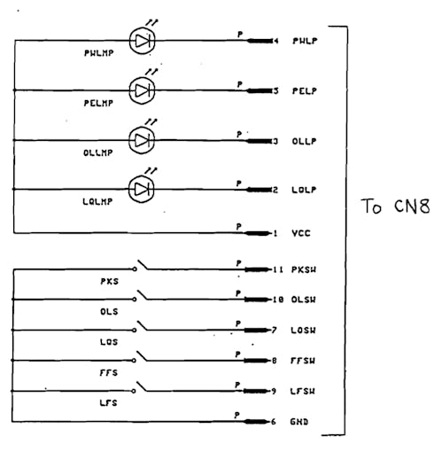
In the service manual, we can see which connector wire goes to which lamp or button:
On top of this, I will probably try to attach a servo on the head, and an additional stepper (from the same printer) or a DC motor for a rotational movement.
I'll add all the documentation as soon as the project is finished.